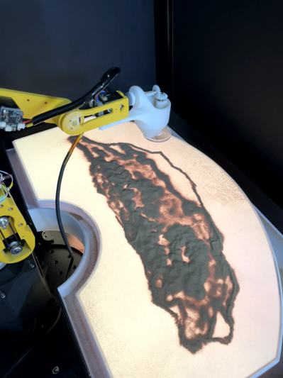
SandArt Robot
A 3D-printable sand-painting robot arm with custom PCBs and biomimetic end-effectors
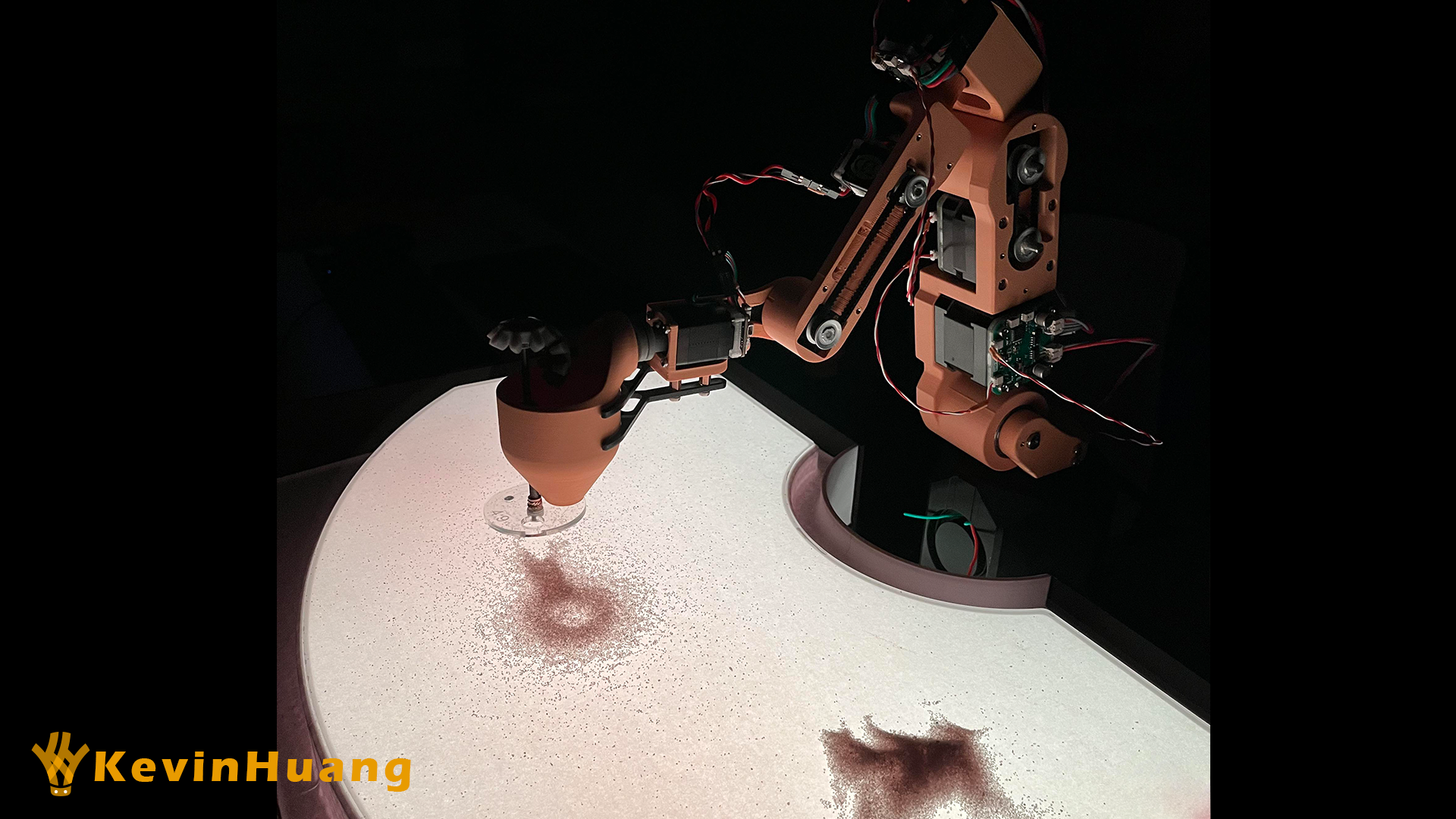
The SandArt Robot builds on the open-source Dummy-Robot by peng-zhihui. We redesigned the mechanics for low-cost 3D printing, developed custom STM32 motor-control PCBs, and created biomimetic end-effectors — a sprinkler and a scraper — purpose-built for sand painting.
Hardware Modification
Mechanical Design
The robot arm is partitioned into six components — Base, Shoulder, Arm, Elbow, Forearm, and Wrist — each redesigned for 3D-printability while preserving repeatability and robustness.
-
Base:
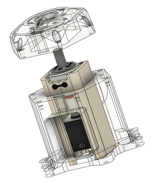
A Sentel harmonic drive (1:50 reduction) drives the base. Additional couplings compensate for misalignment between the harmonic-drive axis and the motor output shaft. The base housing splits into upper and lower halves so that parts can be replaced individually without disassembling the whole robot, and the first axis can be adjusted by hand.
Base Base Structure 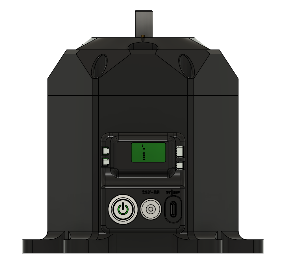
-
Shoulder:
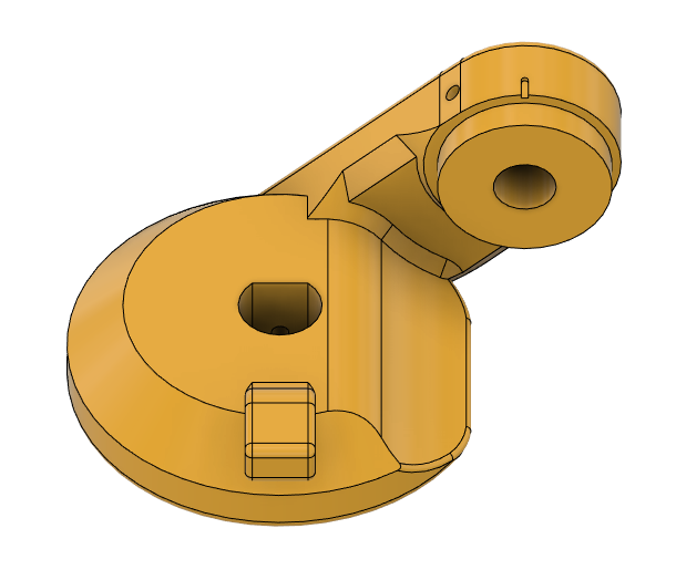
Like the base, the shoulder splits into two parts for easier replacement and better print quality. Extra bearings redirect load from the housing to the base housing rather than through the gearbox. This joint is the most critical — it supports the entire upper arm and must handle rotations from −75° to 90° under varying payload. It is a candidate for CNC manufacturing in a future revision.
Shoulder
-
Arm:
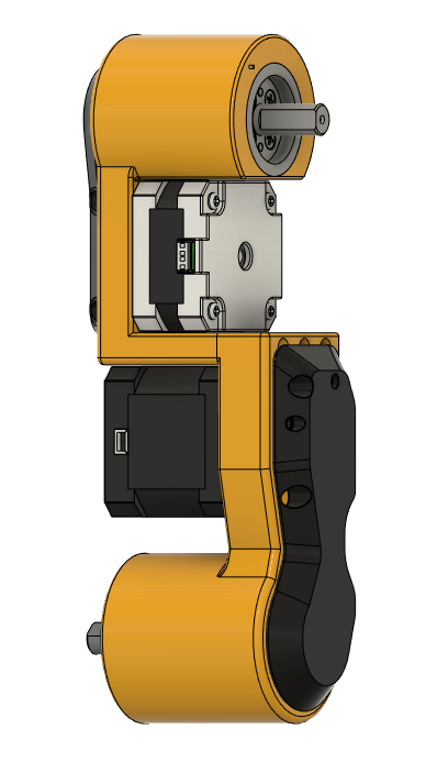
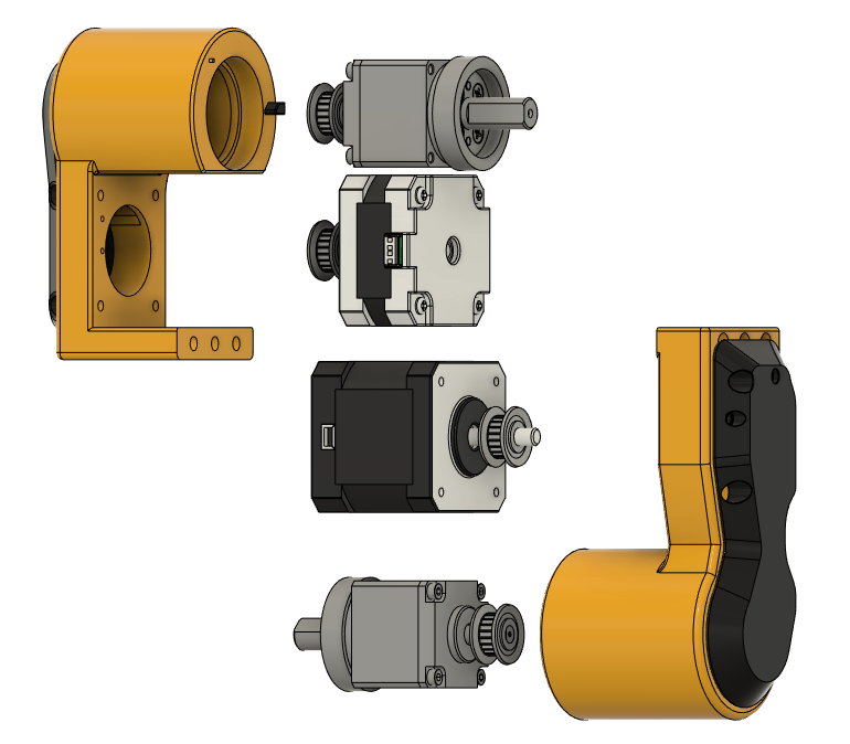
The arm splits into upper and lower halves, joined by three M3 screws for added stiffness. The lower half connects to the shoulder through a bearing for free rotation.
Arm from the front Arm from the side Arm structure 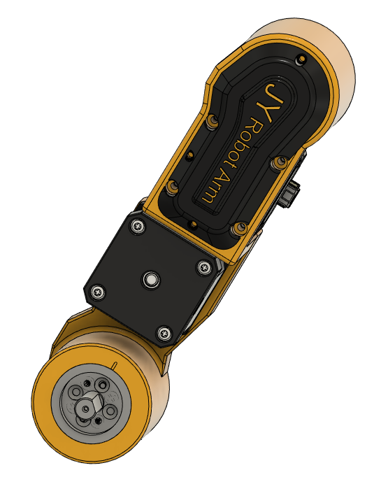
-
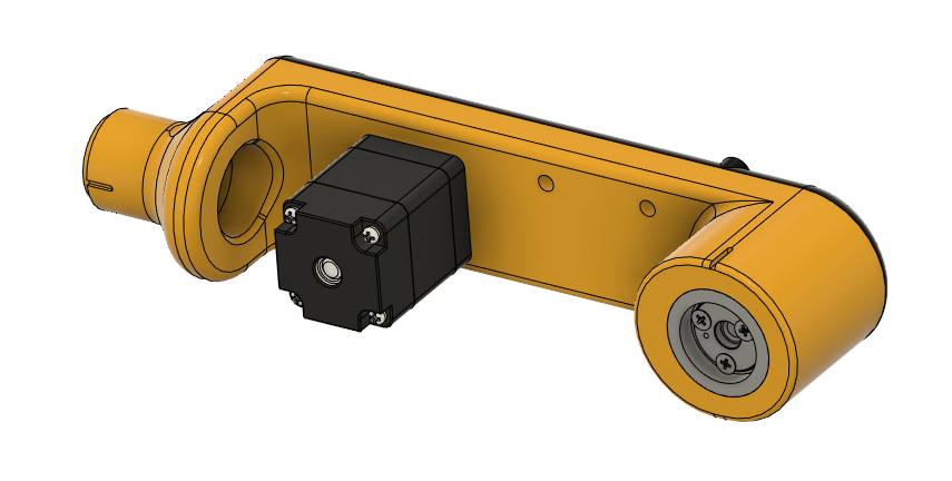
Elbow & Forearm:
These components are straightforward and can each be printed as a single piece.
Elbow Forearm 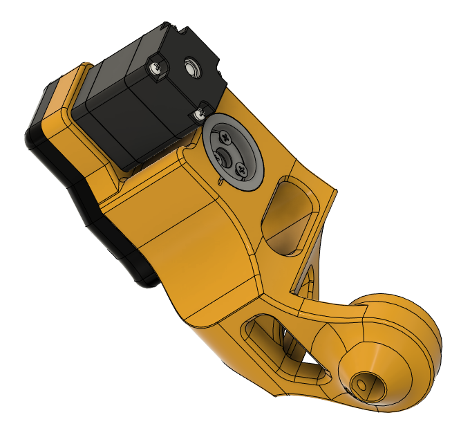
-
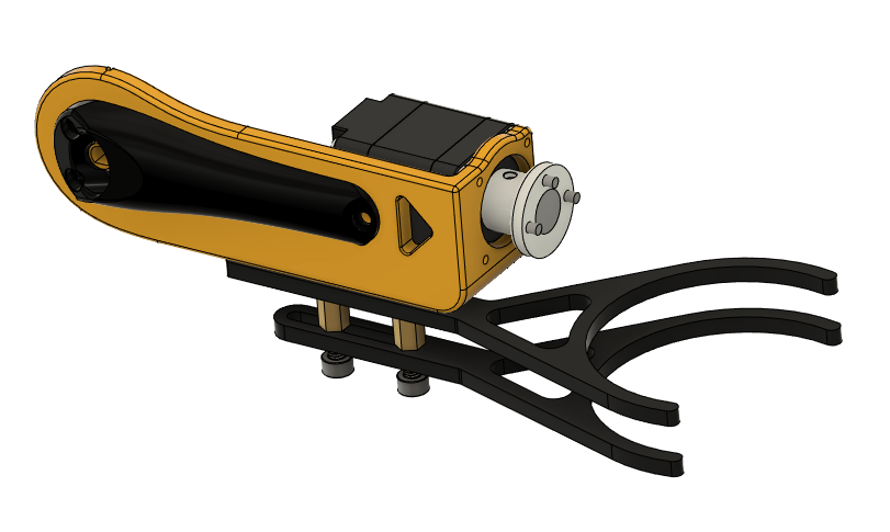
Wrist:
The wrist houses an eye-in-hand camera for closed-loop control and accepts two interchangeable end-effector tools (Sprinkler and Scraper, described below).
Wrist
Electrical Design
Two custom PCBs control the robot’s stepper motors: a 20×20 mm board for NEMA8 motors and a 42×42 mm board for NEMA17 motors. Each integrates an encoder, motor driver, CAN transceiver, and STM32 microcontroller.
-
NEMA17 board grounding fix: After fabrication, flashing calibration data to the MCU failed intermittently. The root cause was a shared analog/digital ground plane — motor-generated noise fed back into the MCU and triggered resets. Separating the grounds (AGND, PGND, GND) with single-point grounding resolved the issue.
-
The NEMA8 board was less affected, likely because the smaller motor generates less noise.
-
Twisted pairs route the CAN bus outside the PCBs to preserve signal integrity.
End-Effector Design
Two end-effectors mimic the two fundamental motions of human sand painting: adding sand (sprinkling) and removing sand (scraping).
An artist cups their palm to carry sand and adjusts the opening between their fingers to control flow rate. For removal, they swipe with one finger, several fingers, or the full palm to vary the cleared area. The sprinkler and scraper replicate these gestures mechanically.
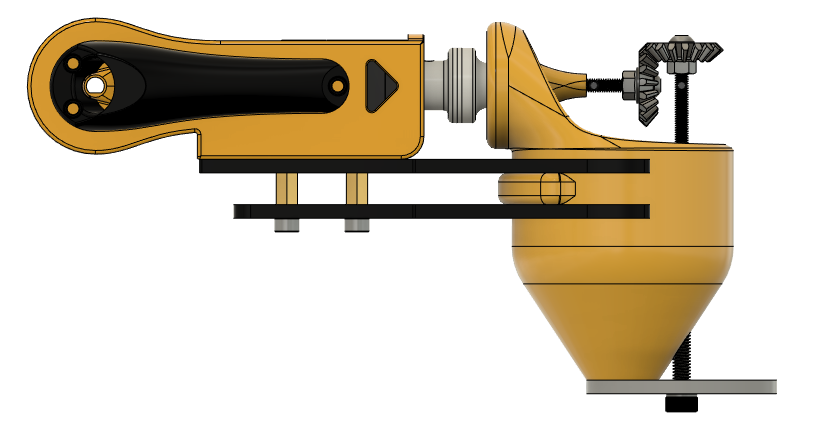
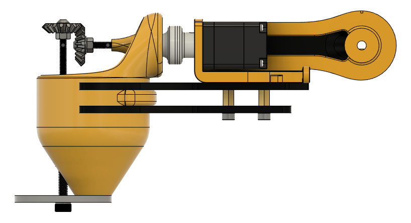
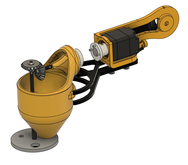
Sprinkler
The sprinkler emulates an artist’s cupped hand. A two-hole plate paired with an hourglass-shaped cup controls the sand flow rate. The wrist’s last degree of freedom actuates it. Earlier iris-door prototypes were abandoned due to leakage.
| Sprinkler side view | Sprinkler side view | Sprinkler disassembled |
|---|---|---|
 |
 |
 |
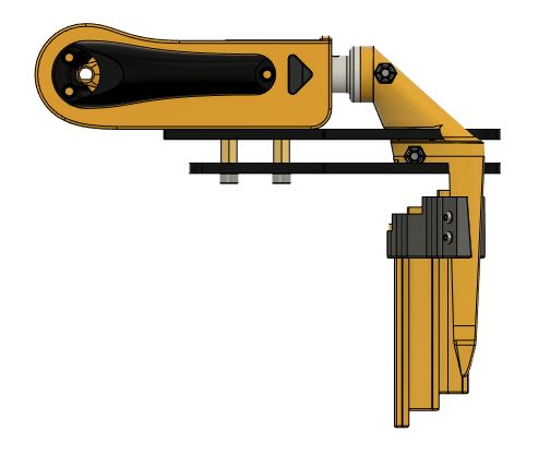
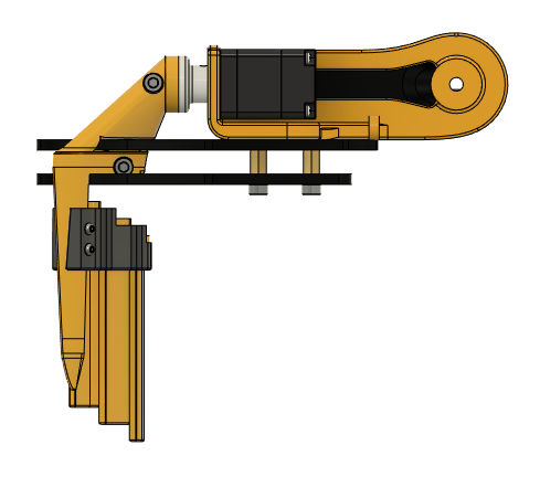
Scraper
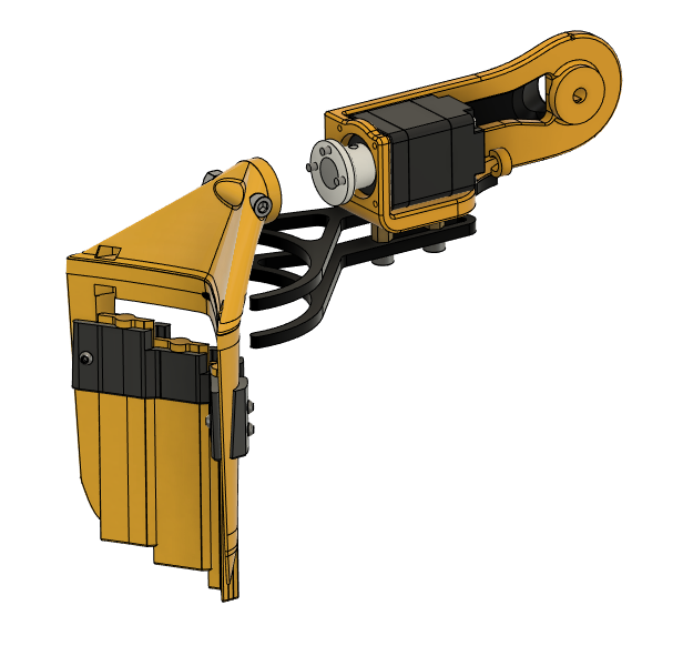
The scraper is a five-section mechanism inspired by the human hand. It adjusts the contact area to control how much sand is removed, actuated by the wrist’s last degree of freedom.
| Scraper side view | Scraper side view | Scraper disassembled |
|---|---|---|
 |
 |
 |
Algorithm Design

Experimental Results
Robot arm manipulation
Sand sprinkling test
Final result demonstration