Light Painting Robot
A 4-DOF robotic arm that creates 3D light paintings through long-exposure photography — UCLA MECH&AE C163A/C263A
Light Painting Robot
A 4-DOF robotic manipulator that creates light paintings by tracing LED paths through 3D space during long-exposure photography. Built as the final project for UCLA MECH&AE C163A/C263A — Kinematics of Robotic Systems, instructed by Dr. Dennis Hong.
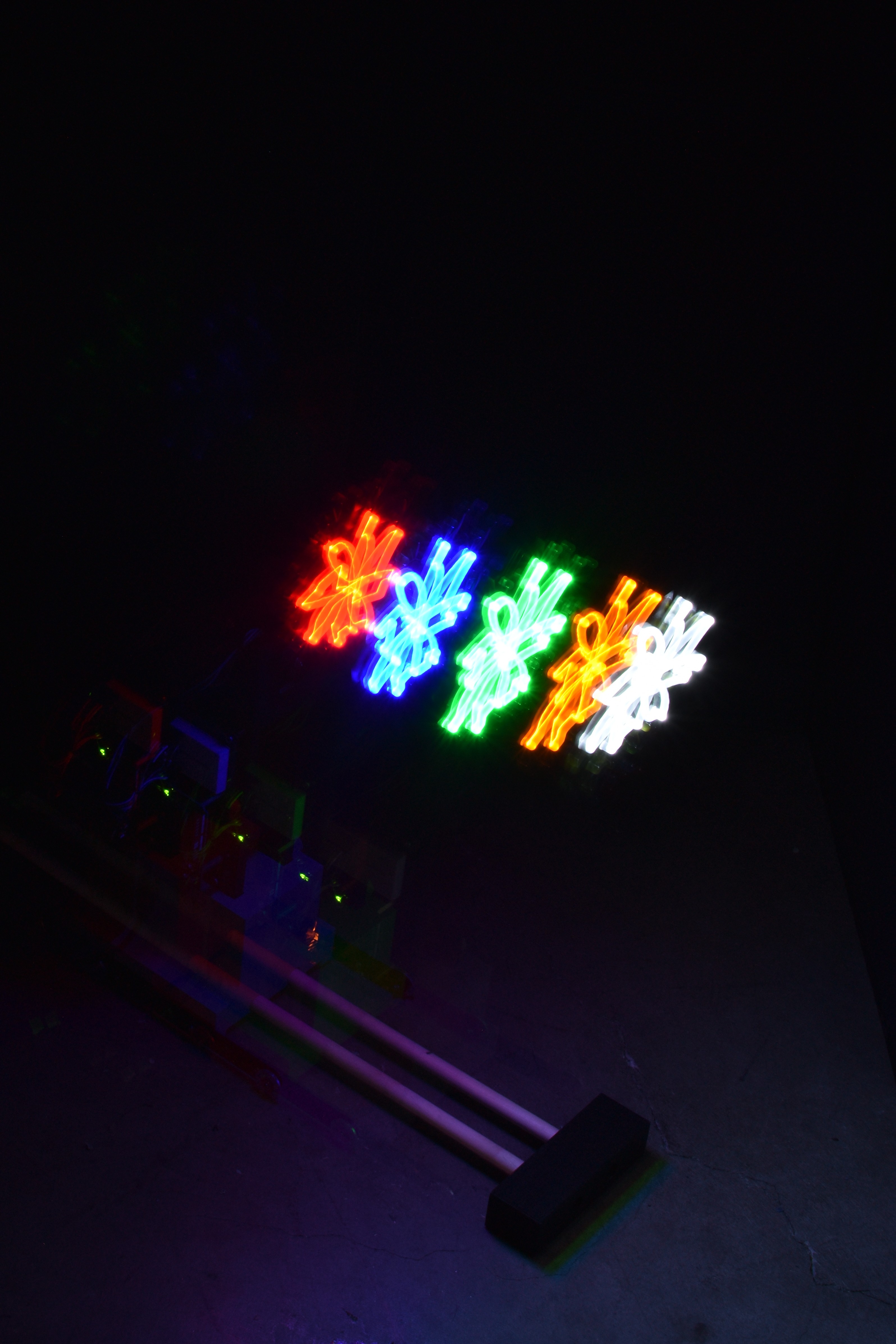
 Five-layer flower — each layer drawn at a different height in a different color
Motivation
The idea was inspired by long-exposure photos of sparklers being traced into pictures on the Fourth of July. We aimed to combine the artistic potential of long-exposure photography with forward and inverse kinematics to design a mechanism that could accurately position an LED in three-dimensional space and trace user-defined patterns with smooth, repeatable motion.
Design
Degrees of Freedom
The robot has 4 degrees of freedom: 3 DOFs for linear positioning (X, Y, Z) of the LED end effector, and 1 DOF for rotation of the end effector to switch between different colored LEDs. A cylindrical workspace was selected to enable 3D light paintings.
Mechanical Structure
The system consists of three mechanical subsystems:
- RRR linkage — a planar three-revolute-joint linkage for X-Y positioning, with a 10-inch radius reachable workspace. The first link is half the workspace radius, keeping the structure compact while maximizing reach.
- Slider-crank mechanism — converts rotary motor motion into linear Z-axis translation. The crank supports full 360° sweep, preserving both elbow-up and elbow-down solutions. Dowel rails guide the linear motion, with oversized holes to reduce friction.
- End effector — a rotary tool-changer holding five different colored LEDs at equal distances from the axis of rotation. Wiring exits from the side with software-limited range of motion to prevent tangling (no slip ring).
Electrical System
The robot is driven by 5 Dynamixel MX-28AR servo motors (2.5 N-m stall torque), controlled through an Arduino Uno connected to a PC. Static force analysis confirmed the worst-case torque requirement of 0.68 N-m is well within the motor’s capability.
Kinematics
Forward Kinematics
Link frames were assigned using the Denavit-Hartenberg convention. The prismatic joint offset d₀ is related to the crank servo angle through the slider-crank geometry. The full forward kinematics chain composes six homogeneous transformation matrices (including base and end-effector offsets) to map joint angles to the LED position in task space. A Space Jacobian was derived for differential control and numerical inverse kinematics.
Inverse Kinematics
The inverse kinematics splits into two independent subproblems:
- Z-axis (1D) — the crank angle θ₀ is found from the desired z-position using the law of cosines on the slider-crank geometry.
- X-Y plane (3 DOF) — the wrist position is computed from the desired end-effector pose, then shoulder and elbow angles are found via polar coordinates and the law of cosines. The wrist angle follows to achieve the desired orientation.
Both geometric (analytical) and numerical (Newton-Raphson) inverse kinematics were implemented. The analytical solution runs at ~4×10⁻⁵ seconds per cycle — about two orders of magnitude faster than the numerical approach (~2×10⁻³ s/cycle).
Singularity Analysis
Workspace-interior singularities occur when both θ₂ and θ₃ are at 0 or π, placing them near the center and edge of the workspace. Trajectory planning avoids these regions.
Simulation
A Python-based simulator validates trajectories before running on hardware. The planner module generates 3D path segments from STEP files and applies sorting algorithms to group nearby segments for efficient traversal. The simulator visualizes the robot drawing the trajectory in a 3D workspace.
Kinematic simulation — the virtual robot traces a flower pattern
Software
The codebase is implemented in Python with a modular class structure:
- Planner — generates 3D path segments from STEP files, sorts segments for efficient traversal
- Motor — wraps a single Dynamixel actuator with PID control (P=900, I=100, D=1000)
- Robot — encapsulates five motors, the kinematics module, and utility functions
- Simulator — visualizes trajectories in a virtual 3D workspace before execution
Source code: github.com/Kevin75311/MAE263A-163A-Final_Project
Results
Long-exposure photos (40 seconds to 5 minutes) were captured with a DSLR on a tripod. 2D drawings were tested first, followed by multi-layer 3D drawings using the Z-axis to stack different colors at different heights.
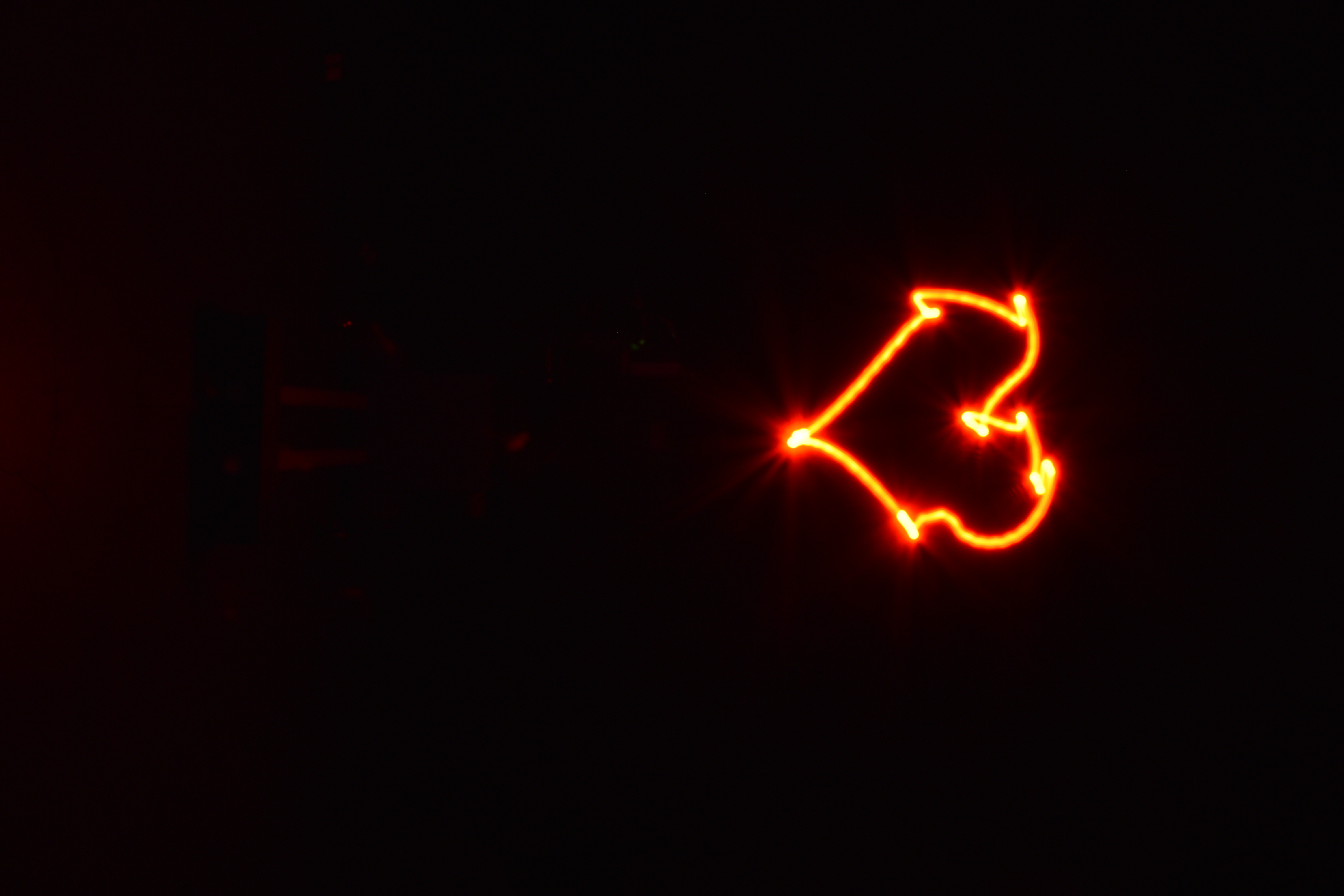
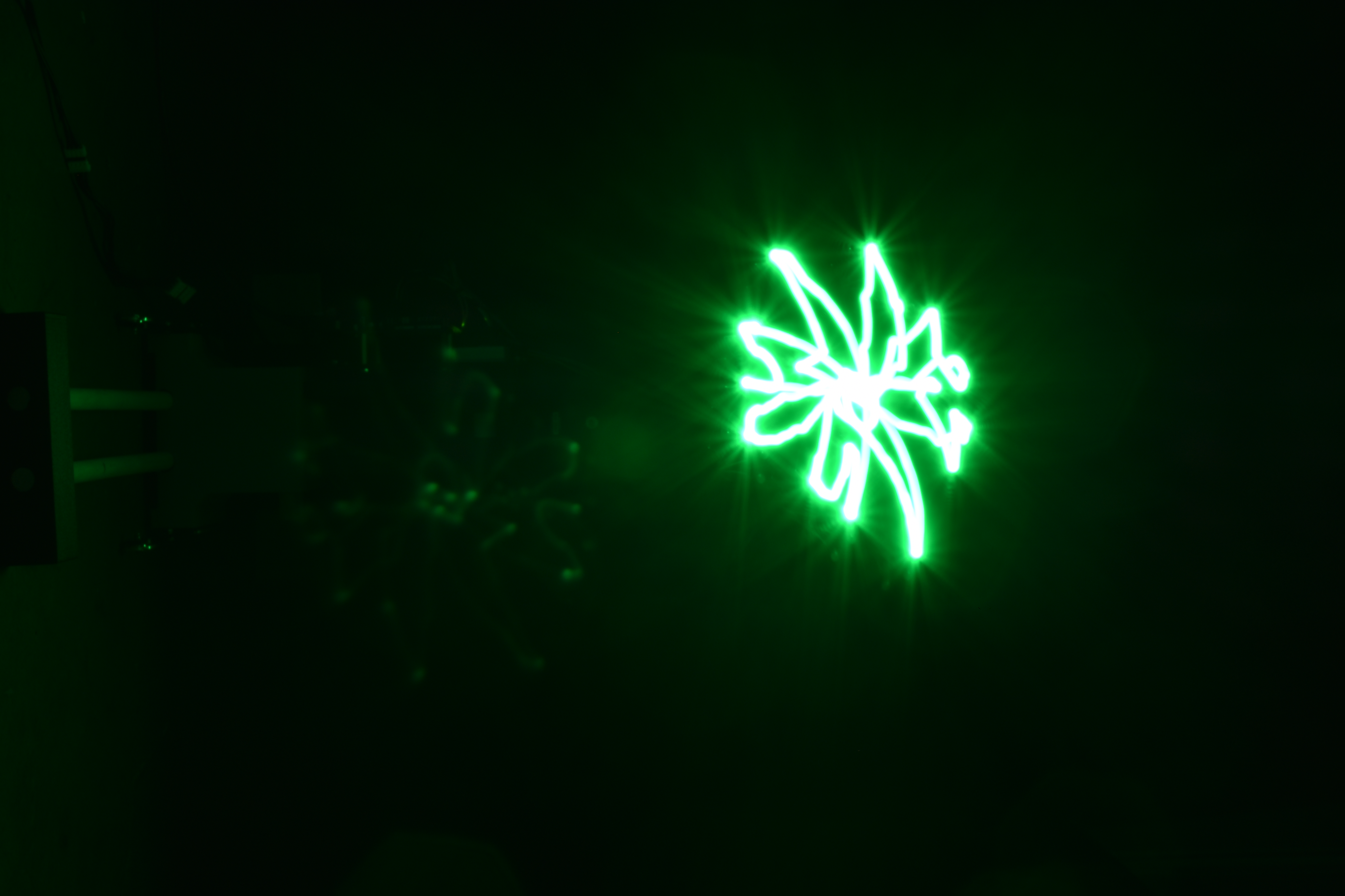
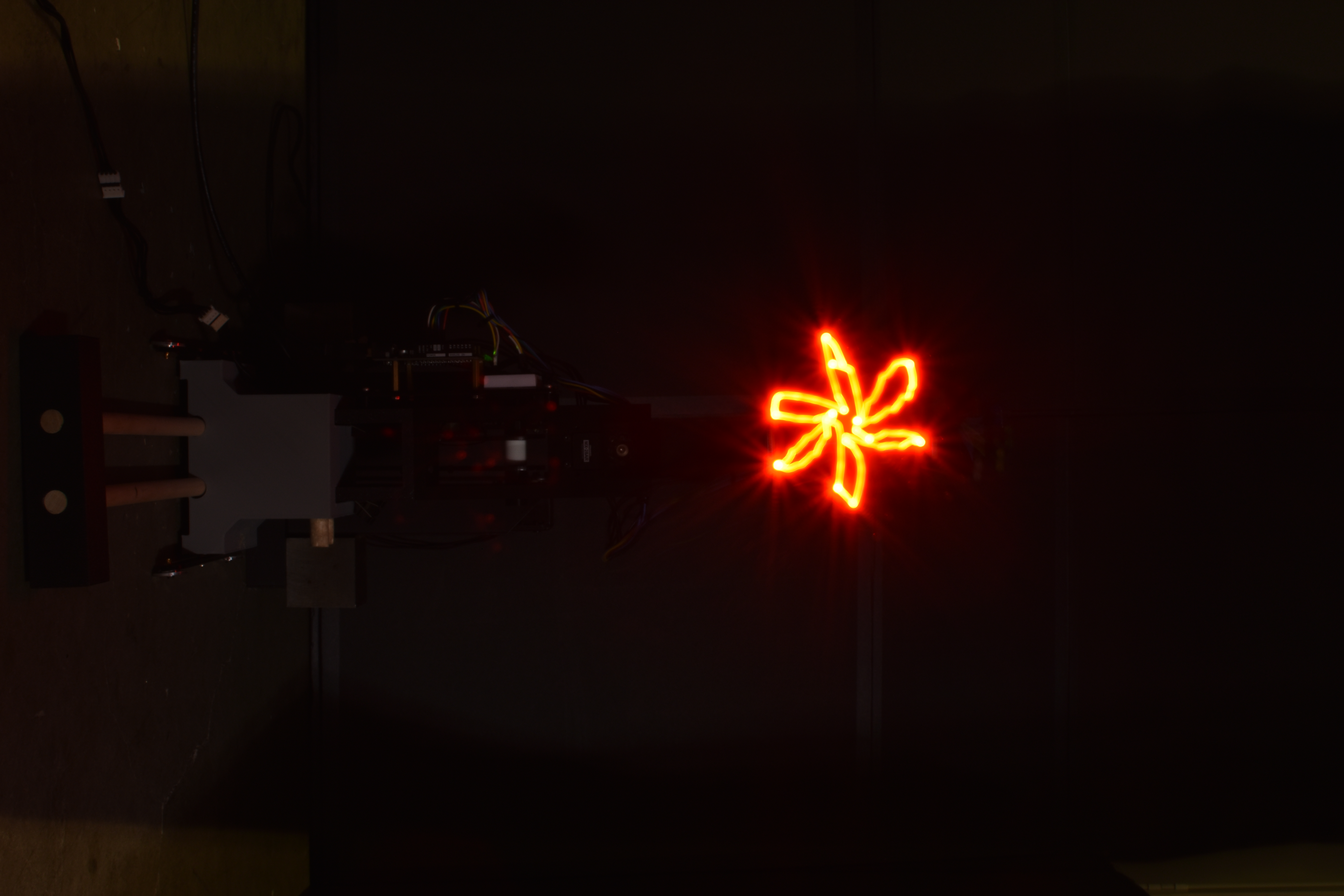
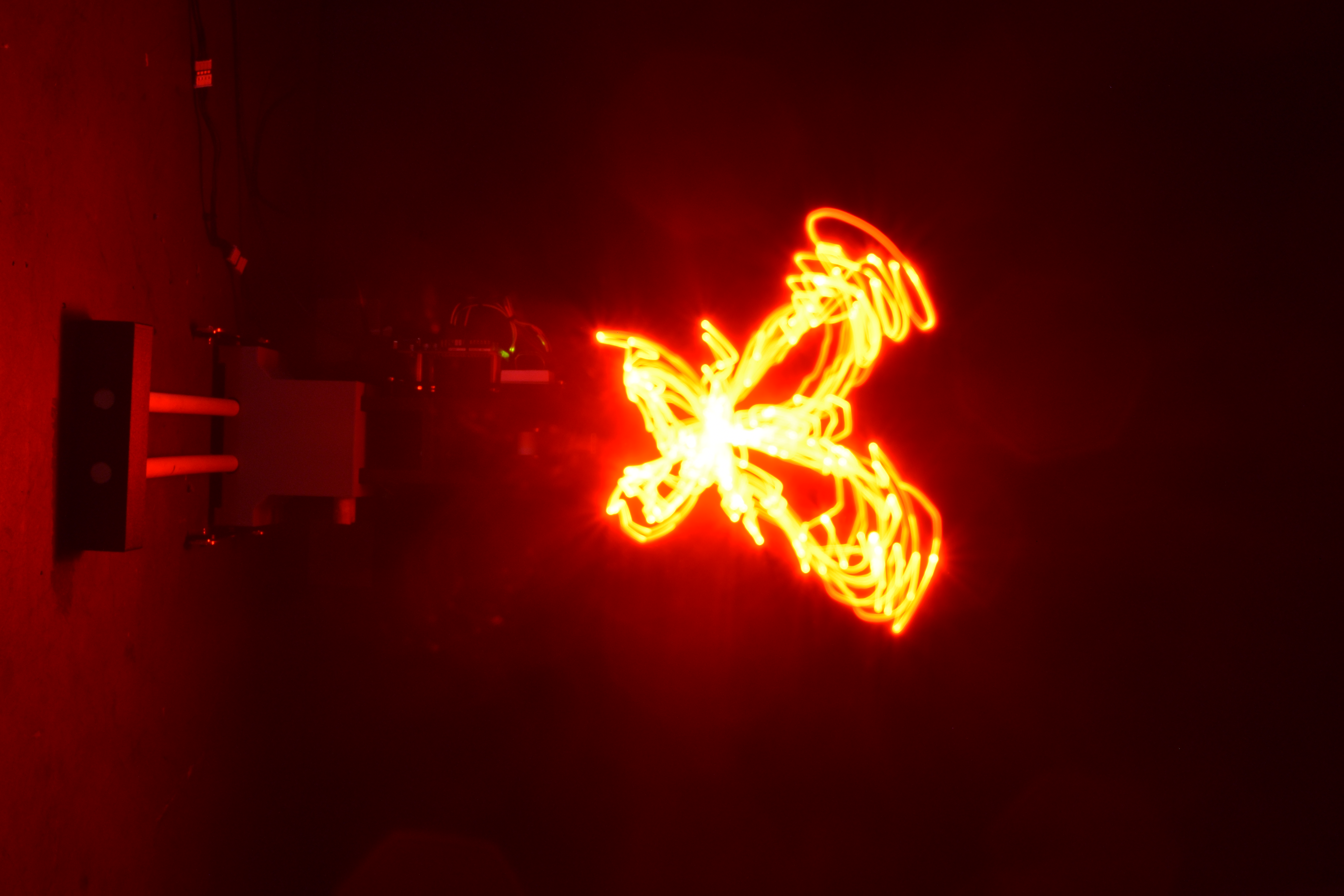
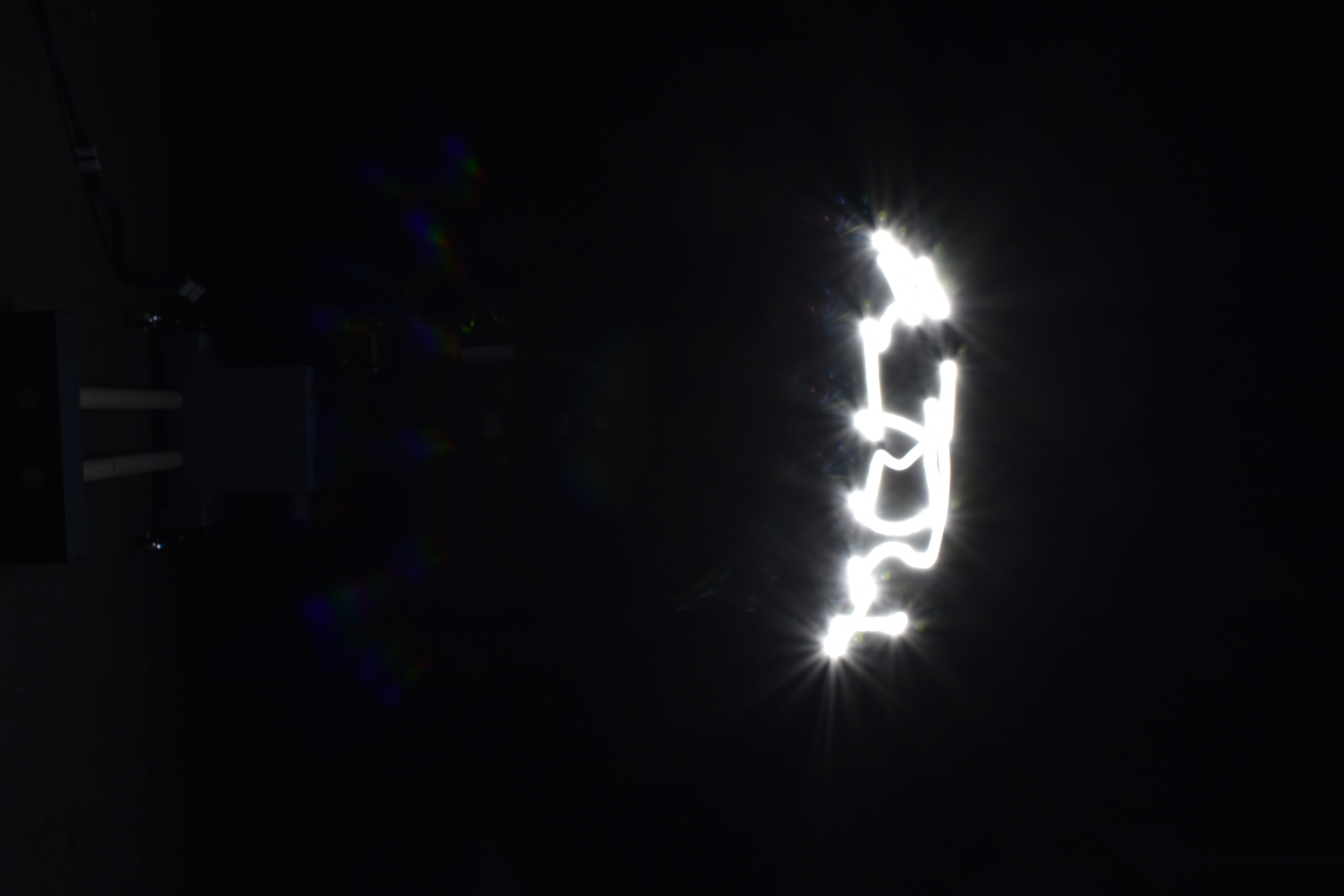
2D Drawings
| Heart | Poinsettia leaf | Red flower | Butterfly | UCLA |
|---|---|---|---|---|
 |
 |
 |
 |
 |
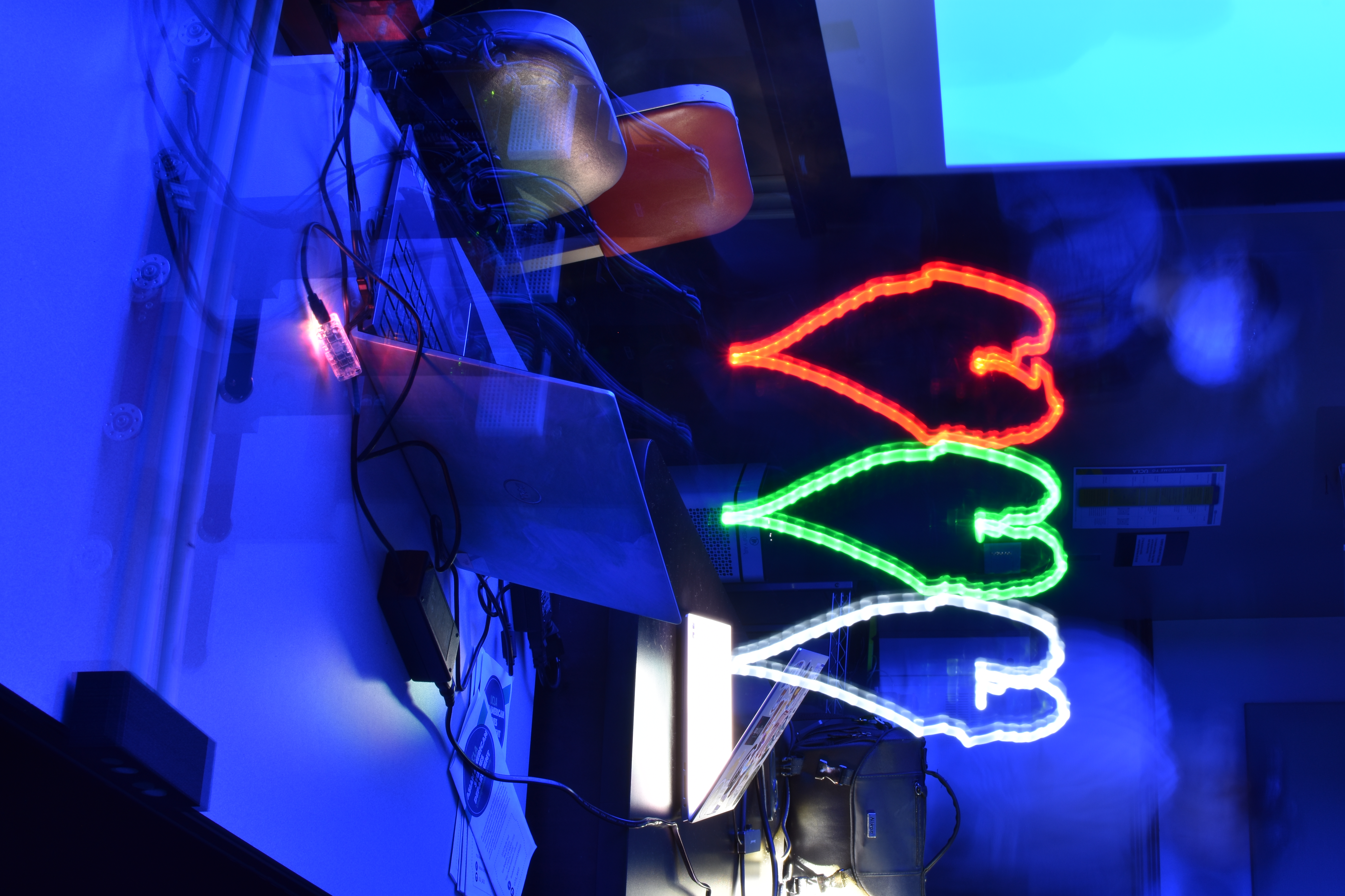
3D Layered Drawings
By utilizing the Z-axis, the same flower pattern can be drawn at multiple heights with different colored LEDs, creating a layered 3D light sculpture.
| Layered flowers — top view | Layered flowers — side view |
|---|---|
 |
|
| Layered hearts |
|---|
 |
Demo Video
The robot drawing layered flowers in five colors